maandag 2 mei 2011

Useful links

To provide a bit of an intermezzo between the posts about building a 3D scanner I thought I might create a list of the most useful internet links I found over the years. Of course if I list links specific to a certain programming language or game engine I would have to pretty much list useful links to all available languages/engines, because different programmers will have vastly different experience in different programming languages, game engines and other things. So I have chosen to provide an as general as possible list of links that are most likely to be useful to everyone.

Though I have no doubt that, when you are done reading, you will shout out: “But what about that other website that I’ve been going to for years!”. I understand this of course and if you are really convinced that it should belong in this list, please put it in the comments and I’ll take a look at it.

I’ve also chosen not to include websites such as google.com or social media websites, because you already know these websites unless you have been living in a cave. And while I’m on the issue of widely known websites let me point out that you probably want to avoid any tutorials found on YouTube. I’ve watched a few and I can say that in the best case these videos are of moderate quality and in the worst case they will actually teach you things incorrectly, so when you do find a proper resource for learning something you actually have to unlearn what the video has taught you before continuing learning something the correct way. So don’t do it! [/rant]

So lets start with a website in the category of seriously-you-don’t-know-about-these?


If you type text related to game development in Google then the odds are very high that you will end up on this website. The thing is though that, using Google, you will usually end up in the forum and although most of the valuable information is there it is not all of the website. If you go the main page you will see a number of dropdown lists at the top. I suggest that you check all of them, especially the resources list.


The Google search results that gamedev.net seems blessed with also applies to stackoverflow.com, but in this case it counts for pretty much any programming related question. As an added bonus, questions you place on this site will usually be answered within minutes, or in rare cases even within less than a minute. The site uses a reputation system which allows people to increase or decrease the reputation of other people for good answers or good questions. Although there is nothing particularly new about this, in the case stackoverflows.com this allows people to access certain privileges such as the ability to vote for an uninformative thread to be closed, editing the posts of other people and ultimately the access to the moderator tools. The website has a lot of other features to, but I’m not going to list them all here.


The news website for game developers. Staying up to date is important and this website will certainly help with that. Except for the main articles in the middle there is also a list of blog posts and opinions to the left. There are sometimes also a few articles that deal with the actual creation of games, although most of it is only news of course. The other major website of game related news is Kotaku, only this site is more gamer oriented instead of game developer oriented like Gamasutra.


The website of game industry veteran Tom Sloper. He has written (at the time of writing) 71 articles on game development. They are aimed towards the beginning game designer but are also very useful for anyone else who is aspiring a career in the games industry, such as game programmers. You can also ask Tom questions and the question and his answer will be posted on his bulletin board so everyone can read it and learn from it.


For pretty much any job in software engineering knowing object oriented programming is a required skill, and since game development is also a kind of software engineering you probably want to learn it. Objectmentor is company that gives lectures and talks about object oriented programming and I guess you could attend one of these if you wanted to, but in my opinion the really useful part of this website is the collection of articles it contains. Go to the resources tab and select articles, then you can select a filter and start reading. Make sure that you read the 5 articles that correspond to the SOLID design principles.

Now it would be unfair if I didn’t mention some other programming paradigms right? Especially the newer ones like data oriented programming and component based programming.


By the way, those two sites are very useful as well, so you might want to check them out too.


This is the guy that created stackoverflow together with Jeff Atwood. The site sports a big amount of very informative articles ranging from articles that help the junior software engineer to articles that give you tips on how to interview a candidate for a software position. He has stopped writing articles though and now spends most of his time promoting his company Fog Creek Software and giving various talks about software development. Jeff Atwood also has a blog called codinghorror but unfortunately it seems to have very little to do with coding these days and has devolved into a site where he either talks about the latest shiny new hardware or is continuously quoting Joel. The older articles might be worth reading though.


I could not leave this out of this list. If there is one mistake that is made by beginning game programmers then it is this. I could elaborate on this but, really, all the information needed to convince someone that writing a requirement-less game engine is a bad idea is right there on that website.

Happy reading!

woensdag 30 maart 2011

Building a 3D scanner part 2

Its been over a month since I last posted here because I’ve been busy with my job and having way too much fun with programming my ascii-rpg (which I will also be doing a blog post about some day). But as you can see I found some time to write part two of how to build a 3D scanner.

Last time I talked about calculating the intersection between a line and plane because those points are needed to reconstruct a 3D model. In that post I said that in order to calculate the intersection point we need to know how a camera projects a point in world space to image space. The projection of this point to image space can be represented by the following equation:


As you can see there are quit a lot of parameters involved in the projection. The vector on the left is the point in image space. The vector on the far right is the point in world space and in the middle are the rotation matrix R and the position vector T inside another matrix. This is the extrinsic matrix which is the position and orientation of the camera in the world. Left to that is the matrix A and this is the matrix that consists of the intrinsic parameters, the ones we are interested in. The equation also contains the scalar s on the far left. This number is a by-product of this projection and is essentially an arbitrary scaling factor needed to balance the equation. It is somewhat related to the depth at which a point in world space lies as seen from the camera.

The intrinsic parameter matrix A consists of the following components:


The αx and αy parameters here are the scaling factors that can be calculated by taking the focal distance and dividing them by the horizontal and vertical size of a pixel on the camera chip. So you expect these numbers to be pretty big (usually around 1000) and that they are roughly the same, because the pixels usually aren’t very rectangular. The u0 and v0 parameters together are the principal point, in pixels. This is the point where the optical axis of the lens intersects with the camera chip. Lastly γ is the skew factor. This is a scalar indicating the degree to which the camera chip looks like a parallelogram. This usually is a very small value.

There are also parameters that affect the projection that can’t be expressed with matrices, because they are non-linear. Among these are the radial distortion parameters, which are the culprits for the fish-eye lens effect that is sometimes seen in photographs. Radial distortion can be described with the following equation:


The parameters k1 and k2 are the distortion parameters and they are also part of the intrinsic parameters. However that’s not what is interesting about this equation. The thing is this equation requires normalized image coordinates which are the x and y parameters. The x and y with the caron sign on top of it are the distorted normalized coordinates. The normalized image coordinates can be calculated by subtracting the corresponding component of the principal point, either u or v, from a image coordinate and dividing it by the corresponding scaling parameter, αx or αy. This normalization is required because radial distortion is applied from the principal point and writing it this way causes the distortion parameters to be independent from the camera chip and to only depend upon the properties of the lens of the camera.

Alright then, so how are we going to calculate all of this? There exists various algorithms for calculating these parameters and most work by giving the algorithm a set of points in world space on an object and a number of sets of those world points projected to image space. The algorithm will then work out which set of camera parameters, both intrinsic and extrinsic, will project the points in world space to image space with the smallest amount of error. The error is calculated by taking a projected point and calculating the distance to the corresponding image point then averaging that for all the point pairs. This is usually called the reprojection error.

A chessboard is usually chosen as a object to generate these points. This is because the corners of the squares of a chessboard are really easy to find in an image with a certain algorithm (I won’t discuss it here but it shouldn’t be too hard to find.) And the points in world space are simply made by measuring a side of a chessboard square. Just take one of corners of the chessboard as the origin of the coordinate system and then they are trivial to calculate.

Writing a algorithm that calculates the camera parameters yourself takes quite a lot of time and effort, but fortunately there already exists an implementation in a open source library. This library is OpenCV and has a great many algorithms related to computer vision, so I made a console application with it that takes a number of images of chessboards and spits out the intrinsic camera parameters. The application can be downloaded at the bottom of this post and also includes a readme because of certain criteria the images must meet.

The application also generates images that show the found points of the chessboards:

To the left is the one of the input images and to the right is image with the chessboard corners marked.

The intrinsic parameters of my crappy webcam are:

αx = 779.336
αy = 792.872
u0 = 341.728
v0 = 265.41
k1 = 0.0223096
k2 = -0.577994

Unfortunately it doesn’t calculate γ so we’ll just have to assume it is zero.

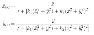
So now that we know the intrinsic parameters we can calculate the mathematical lines that each pixel corresponds to. To do this we must basically apply the projection in reverse, so lets first find a way to remove the distortion from a pixel coordinate. Now coming up with a analytical solution to do this might be a bit hard, in fact multiplying all the variables in the equation until there are no parenthesis left ends up with fith-order polynomial and apparently those are impossible to solve. So we are going to do this with a numeric approximation. Because the distorted coordinates are pretty close to the undistorted coordinates we can use the distorted coordinates instead of the undistorted parameters in the last part of the distortion equation (the part between the brackets). We can get away with this because the normalized coordinates are smaller than one, so squaring them only makes them smaller and have less effect on the result of the equation. Using this, we can rewrite the distortion equation as an undistortion iteration:


Where the i stands for the i-th iteration. At i = 0 the variables with i as a index are equal to their distorted counterparts and at i = ∞ they are equal to their undistorted counterparts. Of course we aren’t going to do an infinite amount of iterations and while testing this iteration I have found that even after 10 iterations the difference between the approximated coordinates and the actual ones is so small that the error is very unlikely to have an effect on anything remotely macroscopic.

Now we can just convert the normalized coordinates to image coordinates by multiplying by the corresponding scaling parameter αx or αy and adding the corresponding component of the principal point u0 or v0. The only thing left is to multiply the image coordinate with the inverse intrinsic parameter matrix to obtain a vector pointing from the center of the camera towards the point in world space that was projected on the image. Don’t forget to normalize the vector.

I also wanted to do a little test to see how well all these equations would work, but that would require a description of the setup and I want to save that for the next post so I will talk about that another time.


zondag 23 januari 2011

Building a 3D scanner part 1

An idea that has been floating around in my head for a while after I graduated is to build a 3D scanner. Mainly because I know how to make one and because it will make for some very interesting blog posts, but also because it will allow me to import objects from the real world into 3D games. Now you might think that something like a 3D scanner needs a whole array of gizmos and doodads, but the principle is surprisingly simple. All you really need is a camera, a line laser and some way to move either the laser or the object to be scanned. Oh, and of course software to calculate the coordinates of the object from the camera images. This image from Wikipedia sums it up pretty nicely.


In the image you can see that there is an angle between the camera and the line laser. This way the further a point on the object is away from the camera, the further to the right the laser line will appear on that point. So the software can analyze each horizontal line of the image and calculate on which pixel position the laser line appears. Note that right will become left if the camera and laser are swapped. Also be aware that this setup with the camera and the line laser is just one way to make a 3D scan of an object, there exist other methods as well such as using two cameras right next to each other and comparing the two images they produce.

So now we know that there is some way to calculate the position on the object where the laser line intersects it by analyzing an image from the camera. I think that the simplest way to calculate the position on the object is to view the line laser as a mathematical (infinite) plane, the pixels on the image of the camera as mathematical rays and calculating the intersection point between the two.

The plane equation in algebraic form is:

         n ∙ p - d = 0

Where:
-          n is the normal of the plane facing away from the center of the coordinate system.
-          p is a point on the plane.
-          d is the smallest distance from the center of the coordinate system to the plane.


The ray equation is:

         pt = u t + p0

Where:
-          pt is the position on the ray at distance t.
-          u is the (normalized) direction the ray is traveling in.
-          t is the distance from the starting point.
-          p0 is the starting point of the ray.

So we solve p = pt by substituting the ray equation in the plane equation and solving for t.

         t = ( dp0 ∙ n ) / ( u ∙ n )

t can then be inserted in the ray equation to obtain the actual intersection point.

So now that we know that how to calculate the intersection point the problem becomes finding out all the values in those equations. The values of the plane equation isn’t such a problem, you can just throw some high school trigonometry at it and calculate the values of d and the components of the plane normal. This is all assuming that you choose the center of the rotating platform in the image of the duck to be the center of the coordinate system. The real challenge lies with the ray equations, or the camera really. The starting position of the rays lie in the center of the lens of the camera and measuring this is rather tricky. Maybe you could get away with a slightly inaccurate position since it only appears once in the total calculation of the intersection point. The direction of the ray however appears twice. Once in the calculation of t and once when inserting t into the ray equation. So we accurately need to know the direction of the ray that each pixel corresponds to. To do that we need to calibrate the camera, also known as camera resectioning, so we know its geometrical properties that transforms a point from 3D Euclidian space to image space. This is what my next blog post will be about. After that I will describe how to build the setup required for the 3D scanner and after that how the software works and processes the images from the camera. Lastly I will test the accuracy and precision of the scanner.


maandag 10 januari 2011

A Sudoku solving algorithm

When I make long trips by using the train I often take a newspaper to try to make the long travel less boring. Unfortunately the contents of the newspaper is not always very interesting, so I end up at the back of the newspaper rather quickly. Luckily that section always contains a lot of puzzles. The most interesting, and time consuming, of them all are usually the Sudoku puzzles. I often solve them without too much effort, but sometimes one of the puzzles is really hard and I am unable to solve it. So I have done what every self respecting programmer would have done: I wrote a algorithm to solve Sudoku puzzles. Now of course there are already a lot of websites that have Sudoku solving algorithms, but where is the fun in using a premade solution?

My algorithm is heavily based on how humans solve Sudoku puzzles. Basically what the algorithms does for each of the 81 tiles is marking whether a number is possible on that space or not. This can be visualized as a 9x9x9 volume of boolean values where the width and length of the volume lie parallel to the Sudoku puzzle and the depth signifies the numbers 1 to 9. This will be called the state volume. In the state volume a value of true means that a number is possible at that tile and false means it is not.


The algorithm works as follows:

  1. Create an empty 9x9 grid, this is called the solved numbers.
  2. Create a 9x9x9 state volume with all elements set to possible.
  3. Put the given numbers of the Sudoku puzzle in a container, these are the new numbers.
  4. Use the new numbers to mark elements in the state volume as not possible. Transfer the new numbers to the correct position in the solved numbers grid.
  5. Search the state volume for new numbers and put them in the container, if they are not already in the solved numbers grid. 
  6. If there are new numbers then go to step 4.
  7. The solved numbers grid contains the solved Sudoku.

Now the most interesting steps are of course step 4 and step 5, because how should we mark the elements as not possible and how should we search for the new numbers? The rules of a Sudoku puzzle say that a number should only appear once in a row, once in a column and once in a square. We also want to mark the elements in the state volume in this way.

This image shows how the fourth slice of the state volume is affected when it is marked by the number 4 in the middle of the puzzle.


The tiles that are now marked yellow cannot contain the number 4. There are also elements that are marked in the state volume that are not shown in this image, namely the elements directly above and below the center of the fourth slice. This is because the number 4 now occupies the center tile on the Sudoku puzzle and this means it is impossible for any other number to exist there.

Searching happens in the same four ways that the volume is marked. Along the rows, along the columns, in a square and in the depth of the volume. In the case of searching along the rows, the algorithm checks for each slice and for each row whether there is only one element in the row on that slice that is still possible. If this is the case then the column and row number become the position on the Sudoku and the depth in the volume becomes the number at that location. Along the columns is almost the same as along the rows of course, just switch the two words. Searching in a square happens for each slice and for each of the 9 3x3 squares. Inside a square at that slice the algorithm checks if only one element is still possible. Searching in the depth happens for each column and for each row.

When I finished coding it and started testing the algorithm I noticed that the algorithm solved the puzzles within the blink of an eye. Also note that the running time of the algorithm, and any other Sudoku solving algorithm for that matter, depends on the number of tiles that are not given. This is of course assuming that the size of the puzzle stays constant. Unfortunately when I tried to solve one of the Sudoku’s on Wikipedia that are marked “Hardest”. The algorithm didn’t work. This was a bit disappointing and I think that due to the fact that the algorithm is based on the methods that humans use when solving Sudoku’s, but I already have a good idea of how to extend the algorithm so it might even solve these puzzles.

Oh, before I forget. The source code below (in C++) simply uses a 9x9 grid as the container for the new numbers. This way I don’t have to make an extra data type to remember the positions on the Sudoku grid. However I do have to search over this entire grid every time I want to mark the elements in the state volume. It is not a big overhead though.